-
Client
BP North Sea
-
Business need
Understanding common failures of gas turbine exhausts to provide key data for re-design
-
Why Frazer-Nash?
During the last 20 years we have worked with a range of clients providing design and analysis for auxiliary gas turbines. This includes Gas Turbine OEMs, package manufacturers and operators. Our extensive knowledge in multiple disciplines enables us to resolve all aspects of a problem including fluid dynamics, manufacturing and installation, and structural design and optimisation.
The challenge
Offshore gas Turbine exhaust systems must support heat recovery and also be light enough to be easily installed or removed, whilst remaining unaffected by cyclic thermal loads and dynamic pressure fluctuations. Failures are common due to the extremes of gas temperature and velocity that occur.
Gas turbine downtime can be extremely costly and remedial measures can involve long lead times and may not address the root cause of past failures. The gas turbine exhaust systems on the Bruce platform have suffered repeated failures during their operating lifetime. BP came to Frazer-Nash to see whether we could determine the shortcomings of the existing design. We then suggested and evaluated design solutions to prevent future failures.
Our solution
We diagnosed the cause of the problems in a three stage process:
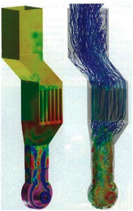
- A Computational Fluid Dynamics (CFD) model incorporating advanced turbulence modelling techniques to capture in detail the pressure fluctuations inside the exhaust system.
- These fluctuations were applied to a structural model of the system to determine local stresses and pinpoint regions of likely failure. A thermal model of the system then determined the stresses generated by thermal cycling during start-up and shut down.
- New design concepts were developed and assessed based on the results of the analyses. This included additional analyses to cover installation and lifting loads.
